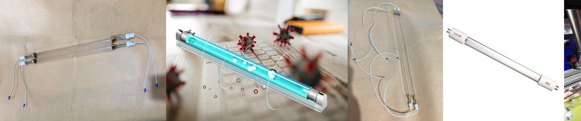

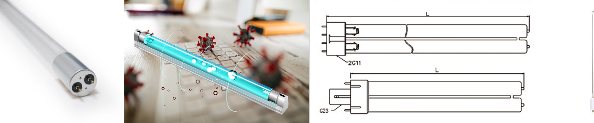
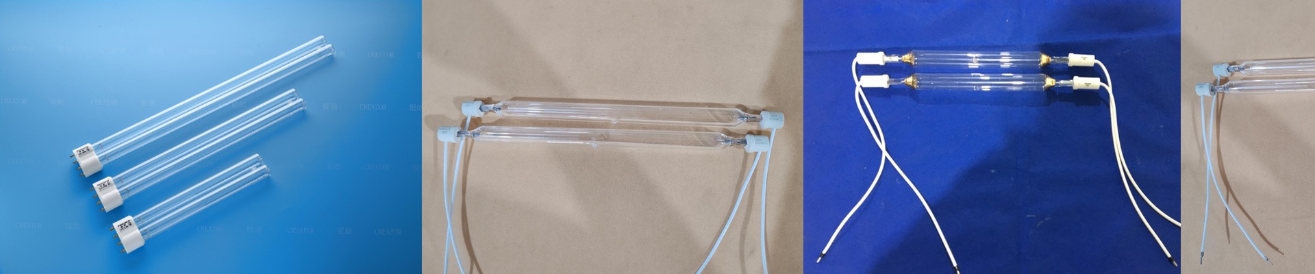
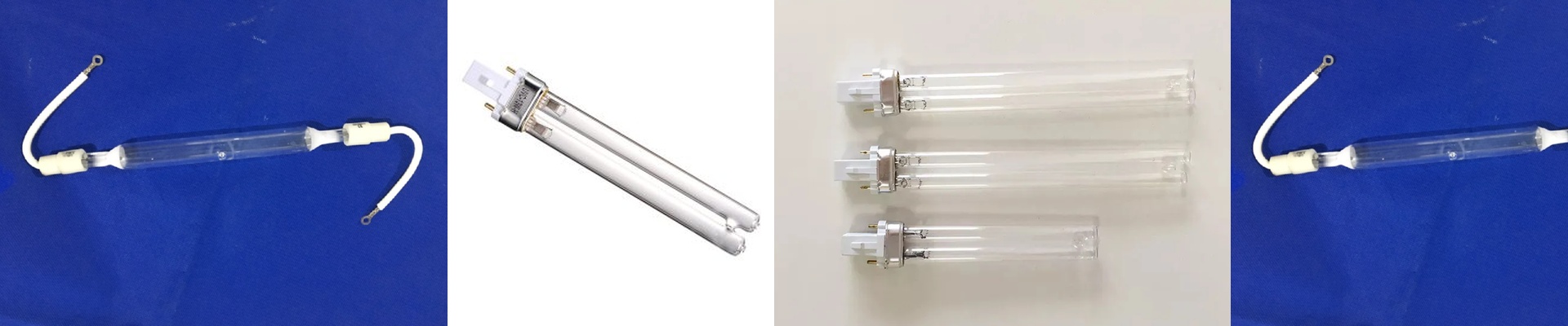
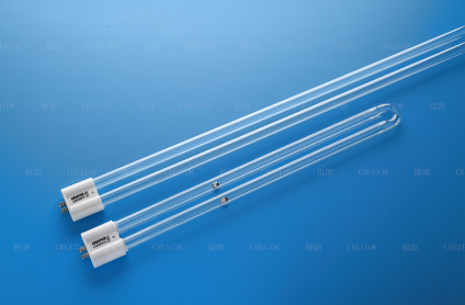
Out on the press floor, the line speed is set and the press is running. The second that UV lamp hits, the ink has to cross-link—fast, clean, and complete. If the lamp circuit isn’t dialed in, you see it immediately: uneven cure across the web, a tacky surface, or a sudden dip in lamp output that forces the operator to back off the speed just to keep the job in spec. In UV curing—whether you’re running mercury vapor lamps, iron-doped lamps, or microwave-driven electrodeless units—the lamp is only as stable as the electrical system behind it. The capacitor in the lamp circuit isn’t just “parts.” It actively shapes current, knocks down transients, and keeps the arc steady. When the capacitor is properly matched to the lamp and driver, the system holds the spectral output the ink chemistry was built around.
What actually matters: capacitor specs that show up in curing performance
UV curing is photochemical, but it runs on electrical engineering. The capacitor teams up with the ballast/driver and the lamp to keep the arc stable—and that stability is what holds wavelength output and peak irradiance in line.
- Voltage rating and dielectric stability under load: The capacitor has to live with the lamp circuit’s operating voltage plus the spikes that come with ignition. Under steady running, dielectric losses heat things up; if the capacitor can’t handle it, capacitance drifts and the lamp current waveform shifts. A clean, stable current waveform supports stable spectral output—especially at the mercury peaks (365 nm, 405 nm, and the other lines) that drive photoinitiator absorption.
- Capacitance tolerance and repeatability: The capacitor value is part of setting the resonant condition in the lamp circuit. Tight tolerance matters because small shifts can push the lamp off its intended operating point, changing power into the arc and altering the lamp’s temperature profile. In the real world, that can show up as drift in 365 nm intensity or a longer warm-up before the lamp settles into steady state.
- Ripple current handling and low ESR: The capacitor sees high-frequency ripple from the driver. If equivalent series resistance (ESR) is too high, that ripple turns into heat, ages the capacitor faster, and distorts current. Current distortion tends to make the arc unstable, which can cut peak irradiance and leave you with inconsistent cure across the substrate.
- Pulse behavior during ignition: UV lamp circuits need a high-voltage pulse to strike the arc. The capacitor helps shape that pulse. If the capacitor can’t manage the pulse without voltage overshoot or ringing, you end up stressing the igniter and the lamp electrodes. Over time, that stress shows up as electrode erosion and shorter lamp life.
- Temperature rating for the actual environment: UV curing units run hot. The capacitor needs to be rated for what’s happening inside the cabinet, not some comfortable lab ambient. A capacitor that’s marginal on temperature will degrade faster, and the driver will end up working harder to compensate—adding variability to the system. None of this is academic. It translates into curing numbers you can measure: consistent peak irradiance at the substrate plane, stable 365 nm output, repeatable energy density (mJ/cm²), and predictable lamp life.
Why it matters on the bottom line: stable performance across the lamp life curve
The application is straightforward: industrial UV lamps in printing and curing, where uptime and repeatability are what pay the bills. The reality is equally clear—people want cost and quality balanced, and they want that balance to hold across the supply chain. A capacitor that performs consistently does two things that hit your operating cost. First, it protects lamp output stability. When the circuit keeps the lamp at its intended operating point, the spectral output stays repeatable day after day. That matters because ink cure is tuned to the photoinitiator’s absorption band. If the driver and capacitor keep the arc stable, you maintain the expected intensity at the key wavelengths, and the cure window stays wide enough to handle normal swings in ink film thickness. Second, it slows the slide in performance. UV lamps don’t fail only when something catastrophic happens; they fail when output drops below what’s needed for reliable curing. A well-matched capacitor helps keep the electrical environment under control, which reduces stress that accelerates electrode wear and output loss. In practice, that means fewer premature lamp changes and less unplanned downtime. That’s where cost and quality stop being a trade-off and start being practical. A capacitor that’s under-specced might be cheaper up front, but it can force the system into a tight operating window. The line slows down to compensate for unstable curing, or the team starts chasing inconsistent gloss and adhesion. Those are hidden costs that compound shift after shift. A capacitor engineered for the UV lamp circuit keeps the system inside the intended envelope. That supports consistent line speed, predictable curing, and a more stable total cost of ownership.
What you need to get right: matching, installation, and the one hard limit you plan around
A capacitor isn’t a one-size-fits-all answer. It has to match the lamp, the driver, and the fixture.
- Match the circuit topology: Lamp circuits vary by lamp type (mercury, iron-doped, etc.) and by driver architecture (electronic ballast, microwave excitation, etc.). The capacitor has to be chosen for the specific topology. Dropping in a capacitor designed for a different driver can shift the resonant point, and that can change how the lamp ignites and how stable the arc is.
- Verify voltage and current at the operating point: Don’t assume a rating is “close enough.” Measure the real ripple current and transients inside the cabinet at full line speed, then confirm the capacitor rating has margin. A capacitor running near its limit ages quickly, and the first sign is often subtle—output drift that only shows up after several hours of running.
- Treat thermal placement as part of the design: Keep the capacitor away from direct hot-spot airflow from the lamp reflector assembly. Heat kills capacitance stability and shortens life. If the cabinet is tight, follow the mounting orientation and spacing guidance for the capacitor’s temperature rating.
- Plan for the one constraint: capacitance is fixed. Unlike driver settings you can tune from the HMI, the capacitor’s value is set. If your process changes—different ink system, different substrate, or a line speed change that demands a different energy density—the capacitor can’t compensate. Either the driver/lamp combination has to be able to meet the new requirement, or you treat capacitor change as part of a documented configuration. Build that into your changeovers. If you’re running UV offset, flexo, or screen with UV inks, that capacitor in the lamp circuit is one of those small parts that quietly controls big outcomes: spectral output stability, repeatable peak irradiance, and how the lamp ages. Treat it as part of the curing system, not just a line item on a parts list. When it’s matched, installed right, and kept cool enough, it helps the lamp fire the way it should—consistently—so the press can run the speed it was set for.